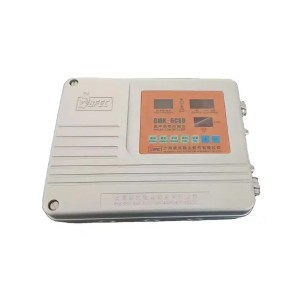
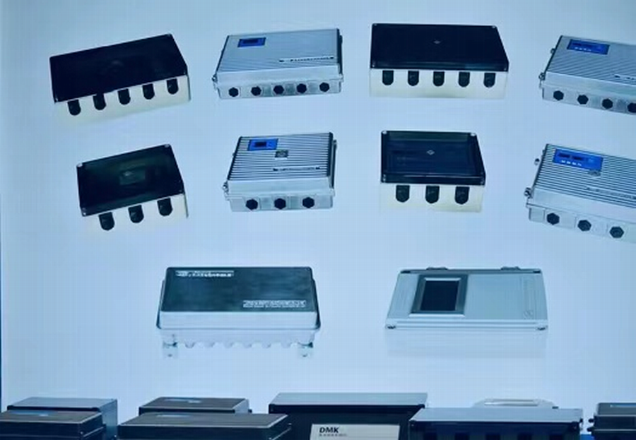
Remote Pulsing Box
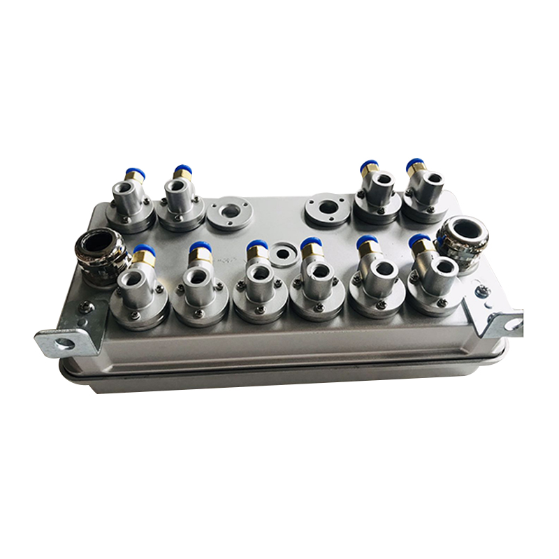
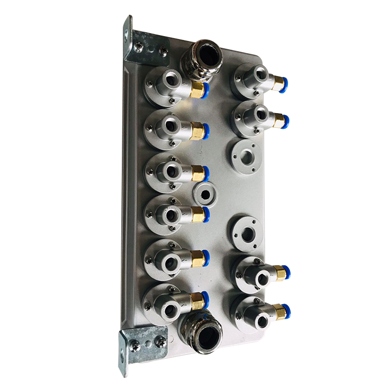
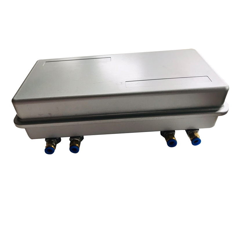
Application:Main control device in injection deashing system of filter. Output drive the Solenoid Pulsing valve, control the compressed air injection and deashing to filter bags in turn. Keep the filter running resistance in setting scope, ensure the good operation and dust collection of filter.
Apply to Bag Filter.
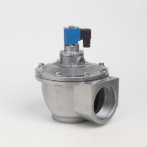
Material:Aluminum Alloy Shell.
Shape:Rectangle.
| Rated Voltage | 220VAC(1 10%)50-60HZ |
| Rated Voltage optionally | 24VDC, 110VAC |
| Rated Output Current | 1A |
| Power Consumption | ≤ 8W |
| Adjustable Range of Output Pulse Width | 10~5000ms |
| Adjustable Range of Output Pulse Interval | 1s~99 hours |
| Adjustable Range of Cycle Interval | 1s~99hours |
| No. of Cycles | 1-9999 loops |
| Use Environment | Relative humidity of air does not exceed 85%
No serious corrosion gas and conducting dust; No acute vibration or shock. |
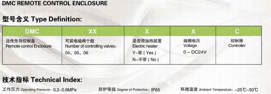
| Model and Specifications | Number to Control Electromagnetic Pulse Valve |
| Connecting to the tube | 6mm, 8mm, 10mm |
| Working pressure | 0.2-0.6mPa |
| Protection level | IP65 |
| Ambient Temperature | -25℃~+55℃ |
| Electric Heating | Y / N |
| DMC-6-Y-24 |
| DMC-12-N-220 |
| DMC-12-N-24 |
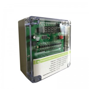
Timer controller is a pulse jet control device that is a main control device in a jet dust-cleaning system of a pulse bag-house. It outputs driving electromagnetic pulse valve, to control compressed air, to jet dust on the filtration bag in a proper sequence, and to keep the operation resistance to clear dust within the set range, so as to guarantee the processing capability and dust-Collection efficiency of the baghouse.
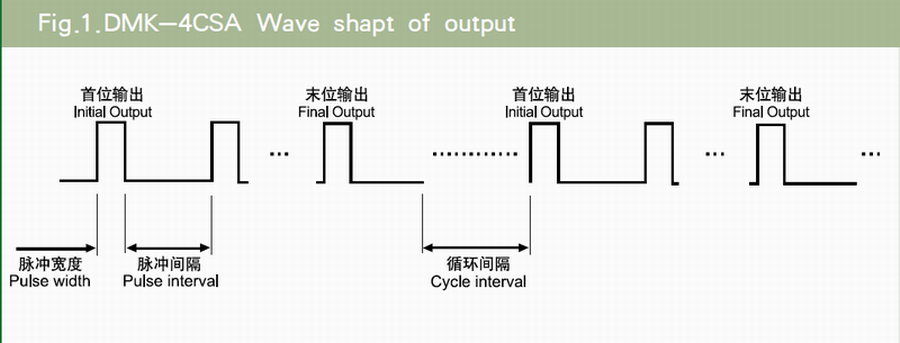
The control device creates driving voltage output every time. One driving voltage has duration, called a pulse width. The interval time between the two-interfacing output-driving voltages is called as pulse interval. The time necessary for the control device to complete electromagnetic valve outputs of all bits is called as pulse cycle. Pause time between the two pulse cycles is called as cycle interval.
Functions:
According to dust-cleaning requirement, cycle interval, pulse interval and pulse width can
be adjusted, to control turning on or off the electromagnetic pulse valve, and to clean dust
in the bag house at a fixed time. Meanwhile, there is differential pressure to control the
input connection point of the control device. When differential pressure of control device is
connected, differential pressure can be set to clean dust at a fixed pressure.
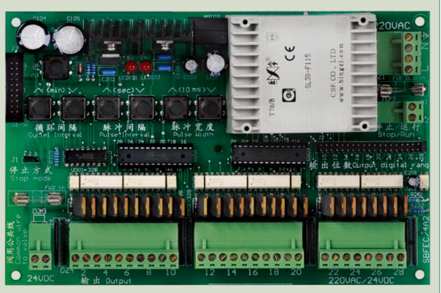
“Manual Advance" key on the PCB can test the working status of the electromagnetic pulse valve in sequence.
Nixie light on the Panel can display timekeeping time during operation and parameter value set during setting parameter.
Special-purpose IC is adopted to simplify the circuit, so as to save components, and improve stability and reliability of the control device.
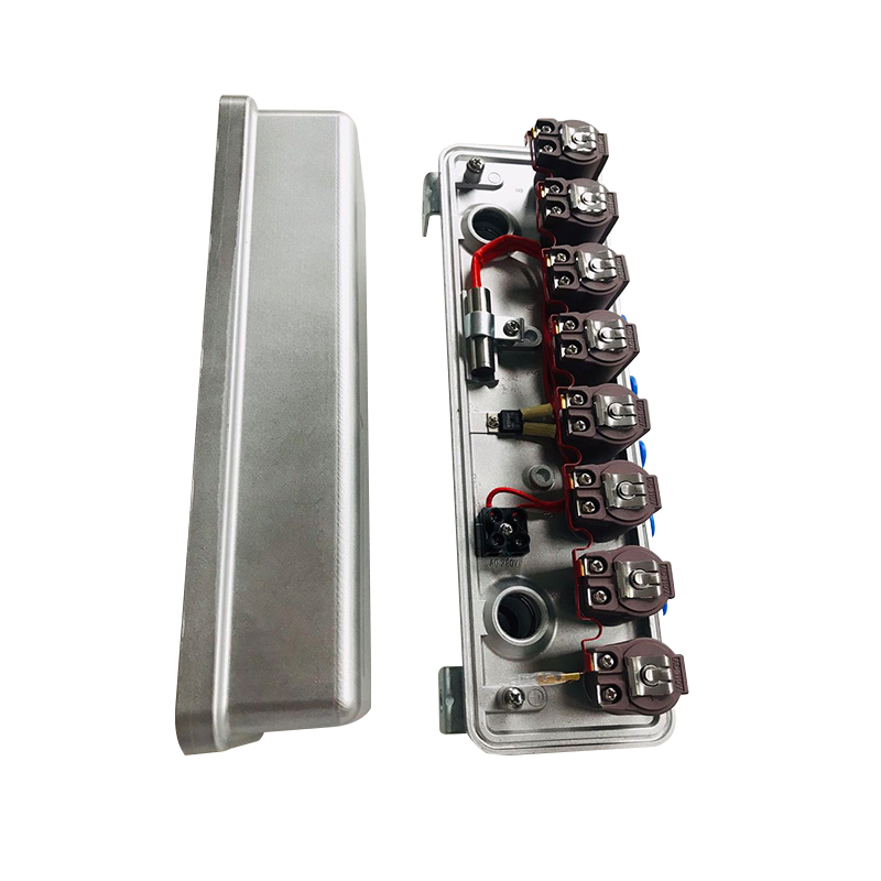
Fully sealed alnico case is used so that its appearance is attractive and dustproof performance is good.
Working Principle
The core control of the control device is performed by a MCU, to realize key-press parameter setting, number display, and control cycle interval, pulse interval and pulse width, so as to control dust clearing operation according to the "Stop/Run" input signal. Every output terminal control turning on of electromagnetic pulse valve and dust clearing with jet compressed air meanwhile nixie light displays jet sequence. The control device is full of functions and is easy to operate.
Technical Index
| Rated Input Voltage | 220VAC(1 10%)50-60HZ |
| Rated Output Voltage | 24VDC |
| Rated Output Current | 1A |
| Power Consumption | ≤ 8W |
| Adjustable Range of Output Pulse Width | 10~990 Millisecond |
| Adjustable Range of Output Pulse Interval | 1~99 Second |
| Adjustable Range of Cycle Interval | 1~99Minute |
| Control Input Signal | Switch Contact |
| Use Environment | -25℃~+55℃Relative humidity of air does not exceed 85%
No serious corrosion gas and conducting dust; No acute vibration or shock. |
| Model and Specifications | Number to Control Electromagnetic Pulse Valve |
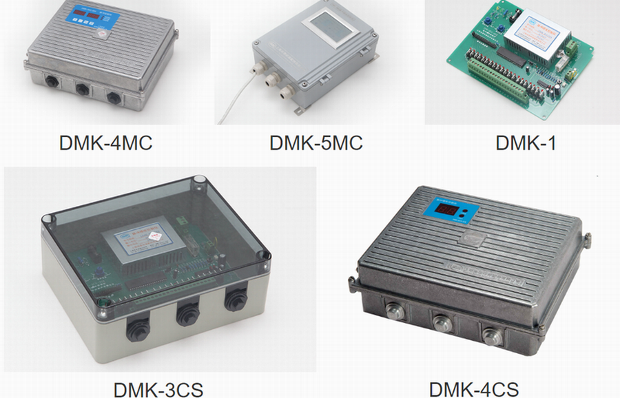
| DMK-(3, 4…6 )CSA 250*192*85mm | 1 to 28 |
| DMK-(3, 4…6 )CSA 370*240*102mm | 30 to 72 |
| DMK-3CSA-5 | DMK-3CSA-15 |
| DMK-3CSA-6 | DMK-3CSA-16 |
| DMK-3CSA-10 | DMK-3CSA-20 |
| DMK-3CSA-12 | DMK-3CSA-25 |
| DMK-3CSA-13 | DMK-3CSA-30 |
| DMK-3CSA-14 | DMK-3CSA-35 |
| DMK-4CSA-5 | DMK-4CSA-15 |
| DMK-4CSA-6 | DMK-4CSA-16 |
| DMK-4CSA-10 | DMK-4CSA-20 |
| DMK-4CSA-12 | DMK-4CSA-25 |
| DMK-4CSA-14 | DMK-4CSA-30 |
| DMK-6CSD-6 | DMK-6CSD-15 |
| DMK-6CSD-12 | DMK-6CSD-20 |
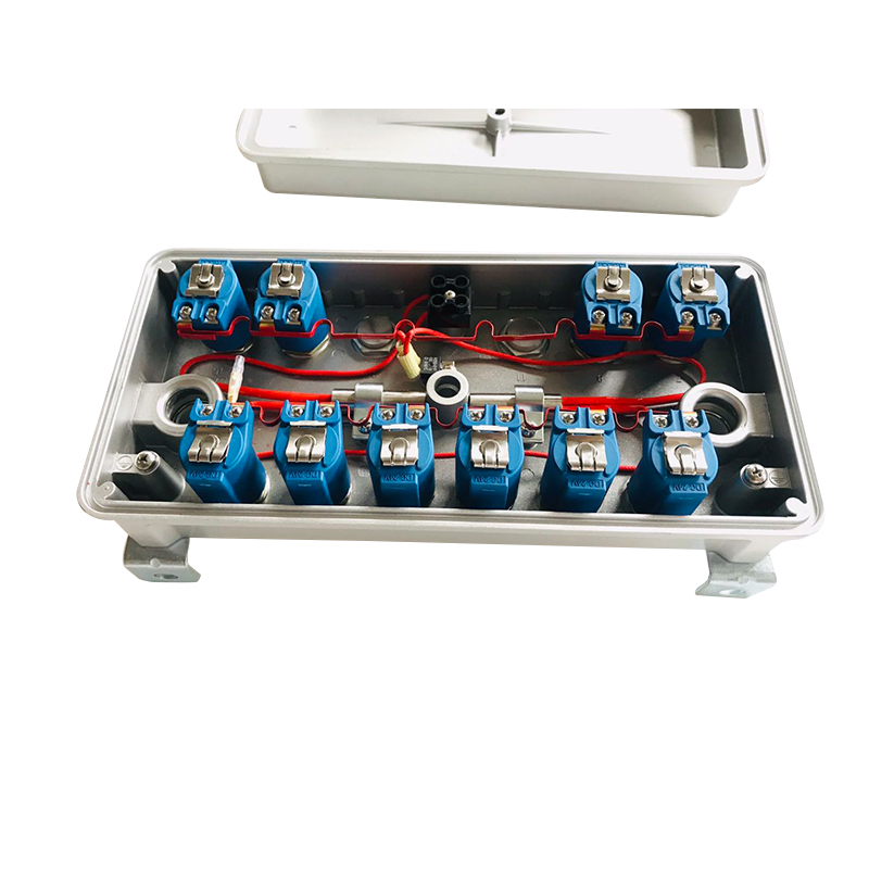
It is recommended to use a copper cable not less than 0.75 mm2, with seal joint. It goes through the knockdown hole on the control device case, which should be not too tight and not too loose, to avoid damage and affect seal performance. See Fig. 5 for wiring method.
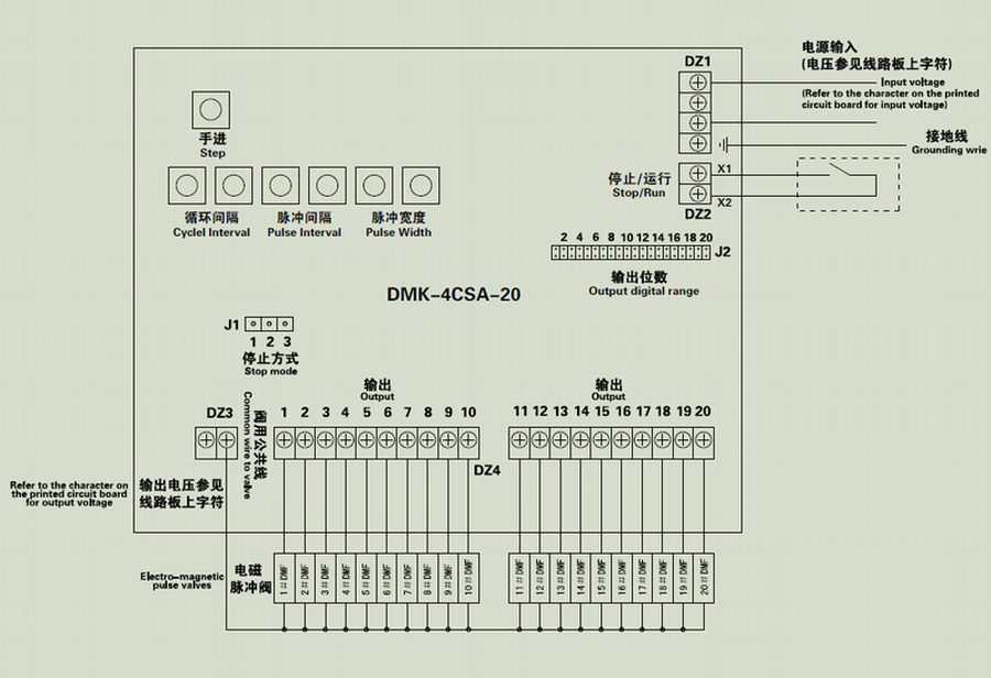
The control device adopts a connection terminal of inset and pull type. When circuit board is replaced, it is not necessary to remove all connection leads, but only to pull out the plug so as to save maintenance time.
Manual
Run Control:
After power on, the input terminal of “Stop/Run” on the circuit board has the following:
(1)The contact of external connection is not closed, and the control device stops operation, to wait for the contact to close;
(2) The contact of external connection is closed, and the control device starts operation. starts to output driving pulse valve from the 1st digit. After the pulse is delayed by a pulse width, it stops output. Then after pulse interval is time-kept, it shifts to the next digit to output and then to the last digit and pulse output stops. After cycle interval is time-kept, the 1st digit starts to output again, and a new cycle starts.
Stop Mode:
When control device is operating, and if the contact of external connection on input terminal of “Stop/Run” on the circuit board is disconnected, there are 2 stop operation modes:
(1) J1 insert block on the circuit board makes pin 1 and pin 2 joined, and the control device stops operation at once. If external contact of input terminal of “Stop/Run” on the circuit board is closed again, the next digit, from the last time when operation stops, continues output operation.
(2) J1 insert block on the circuit board makes pin 2 and pin 3 joined, and the control device does not stop operation at once, and stops operation until the last digit output of the control device. If external contact of input terminal of “Stop/Run” on the circuit board is closed again, it starts to continue output operation from the 1st digit.
Time nixie light display:
Under control operation, display is the remaining timekeeping of pulse interval or cycle interval; if nixie light display is blinking, the display is the remaining time of cycle interval; if nixie light display is not blinking, the display is the remaining time of pulse interval; if operation stops, the display is“0” when a parameter is set up, the display is the set parameter value.
Step output:
Pressing “Step” key on the circuit board can stop the current pulse interval timekeeping, to go to the next pulse valve driving output at once. In this way, the working status of the electromagnetic pulse valve can be checked in sequence quickly.
Maximum output digit:
There is a selection short connection block of maximum output digit for control device, to move J2selection insert block to the required socket of the output digit and make the upper and down pins on the location jointed, so as to realize the required selection of maximum output digit.
Pulse width parameter:
“∨”and “∧”key is pressed at “pulse width” on the circuit board, pulse width parameter can be adjusted between digits 1~99. The parameter unit is 10 millisecond, and the adjustable range of the corresponding pulse width is 10~990 millisecond.
Pulse interval parameter:
“∨”and “∧”key is pressed at “pulse interval” on the circuit board, pulse interval parameter
can be adjusted between digits 1~99. The parameter unit is 1 second, and the adjustable
range of the corresponding pulse interval is 1~99 second.
Cycle interval parameter:
“∨”and “∧”key is pressed at “cycle interval” on the circuit board, cycle interval parameter
can be adjusted between digits 1~99. The parameter unit is“minute”. Adjustable range of
the corresponding cycle interval is 1~99 minutes.
Parameter saving:
Under parameter modification status of control device, timekeeping and pulse output stops. For the above 3 parameters, when “∨”or “∧”key is pressed for the 1st time, the display on the nixie light is the original parameter value. After afterwards pressing, the display is the modified parameter value; if there is not any pressing “∨”or“∧” key in 3 seconds, the parameter value of the current modified value is saved, and the control and display return to the status before the parameter is modified, and the modified parameter controls operation. When any parameter is under modification, another parameter can be modified at any time and the modified parameter is all saved during saving period.
After sales maintenance situation and solution
| After the control device is powered on, 5V, 24V nixie light indicator on the circuit board is not lit. It is necessary to check if power line is loose with connection terminal, if 0.315A fuse of power supply is broken, if power transformer is normal and if there is any phenomena like a broken line, loose soldering, etc. in the power supply part. |
| If 5V LED indicator is not lit, it shows that there is a short circuit in the load, and some component is damaged. It is necessary to check one by one. If load is disconnected, 5V is still abnormal, and 3-terminal stabilized circuit must be checked to see if it is normal. |
| If 24V nixie light indicator is not lit, the general status is that there is overload or short circuit of electromagnetic pulse valve and lead at the load side. |
| After the control device is powered on, nixie light display and key input is normal:
Output nixie light indicator is lit and electromagnetic pulse valve does not work. And it is possible that the corresponding electronic switch tube is damaged |
| If an electromagnetic pulse valve is always magnetized, it must be checked if the corresponding electronic switch tube is in electric leakage or broken-down. |
| If electromagnetic pulse valve is not always magnetized, it must be checked if the connection outside of the terminal of common lead of the valve is correct and reliable. |
Parameters
| Items | information |
| Code | DMC-6-Y-24 |
| Design | Pulsing controller with pilots |
| Screen | on line |
| Temperature reading | Available |
| Advantage | Remote controlling 6 digits |
| Working temperature | -25degre to 50 degree |
| Protection level | IP65 |
| Working Pressure | 0.2-0.6MPa |
| Voltage | 220VAC, 24VDC |
| Medium | Clean air |
| Pusling interval | 1second -99hours |
| Optional Function | with heating system |
| Voltage | 24VDC |
| Optional digits | 5-20 |
Trading information
| Trading information | Logistic information | |||||||
| Description | Piece/Pieces | FOB price | Payment terms | Qty less below Pieces |
Delivery time | Port | Monthly Piece/Pieces |
Packing |
| Remote enclosure box 24VDC | <20 | 119 | T/T,Western Union,MoneyGram,Paypal | 20 | 20 | Shanghai | 100 | 1pc/box |
| 20-100 | 104 | |||||||
| >100 | 100 | |||||||