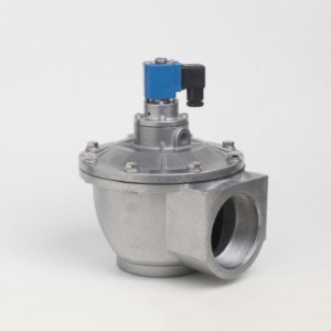
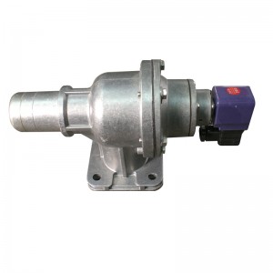
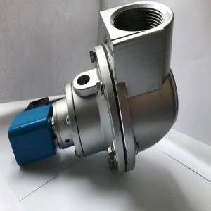
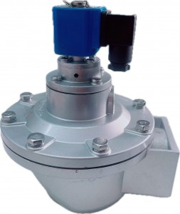
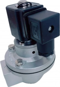
DMF-Z-2-40 Pulse valve Right Angle Threaded pulse jet dust collector
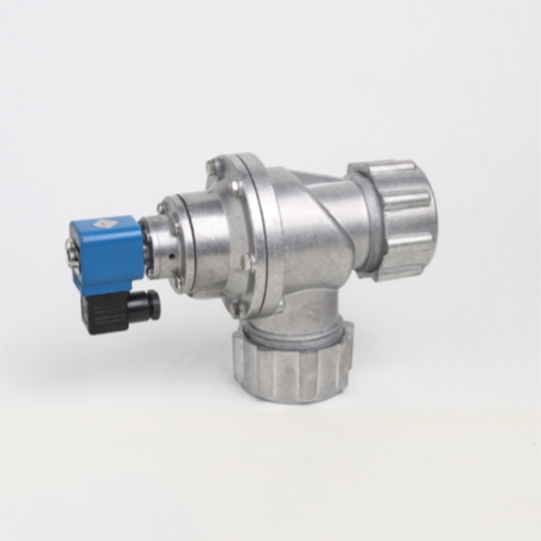
Pulse diaphragm valve (also called Electro-magnetic valve) is the "switch" for compressed air in the dust clean blowing system of the pulse bag filter. Controlled by the output signals of the pulse jet control device, it makes dust clean to the filter bags cell by cell to keep the resistance of the baghouse within the set range and thus guarantee the processing functions and the dust-collecting efficiency of the baghouse. DMF-Z- electro-magnetic pulse valves are right angle valves (also threaded ones) which are directly installed on the manifold box. They have better flow characteristics and operate with reduced pressure loss, therefore, the are suitable for conditions where the pressure of the gas source is relatively low.
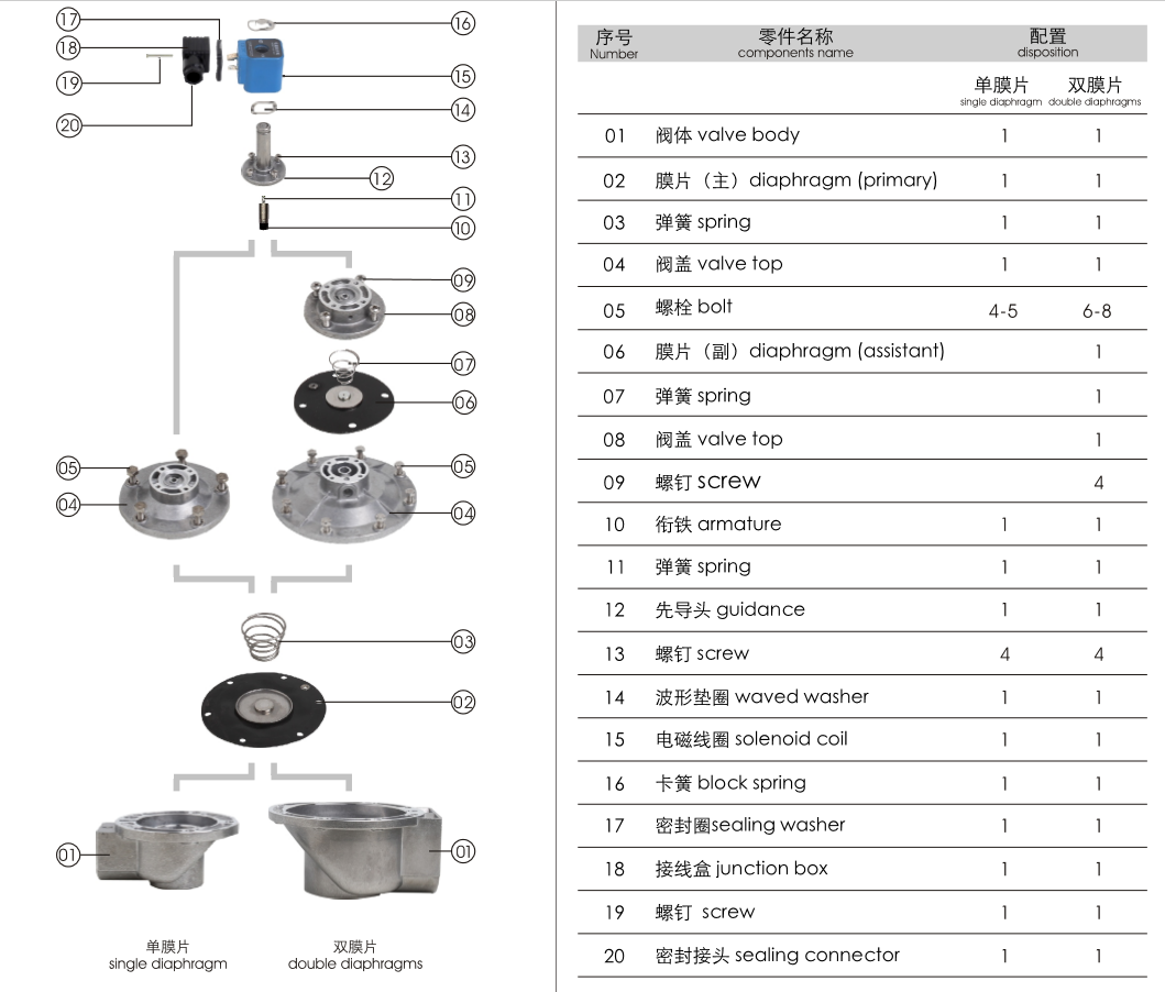
Working Principle
The electro-magnetic pulse diaphragm valve is composed of two gas cells. When the compressed air is connected, it comes into the back-gas cell though the orifice.
The pressure in the back-gas cell pushes the diaphragm closely against the outlet of the valve and the electro-magnetic valve stays in the "closed" condition.
The electrical signals from the pulse jet control device move the armature of the electro-magnetic pulse valve. The air escape of the back-gas cell opens and the back-gas cell loses pressure quickly, thus the diaphragm moves back and the compressed air blows through the valve outlet. The electro-magnetic
pulse valve comes into the "open" condition.
When the electrical signals from the pulse jet control device disappear, the armature of the electro-magnetic pulse valve returns to its original position. The air escape of the back-gas cell closes and the pressure in the back-gas cell rises, which pushes the diaphragm closely against the valve outlet. The electro-magnetic valve comes into its “closed” condition again.
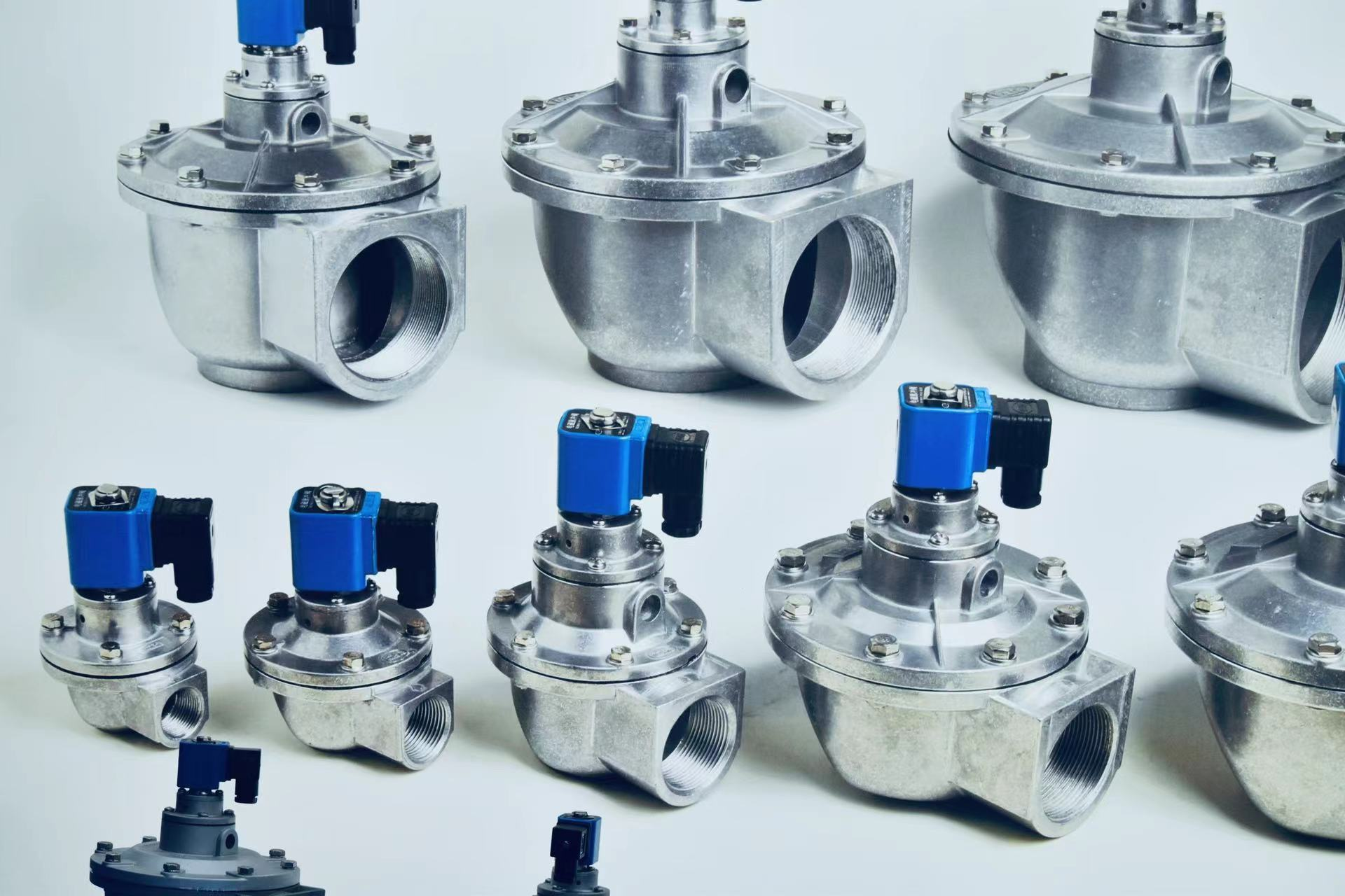
Type and Specification
| Inner Type | New Type | Diameter mm | DiameterInch | Main Diaphragm mm | Outer orifice connection mm | Blow pipe inner Diameter | Weightkg | Kv/Cv |
| DMF-Z-20 | DMF-Z-1-20 | Ø20 | 3/4” | 80 | 27 | 20 | 0.65 | 17.55/20.48 |
| DMF-Z-25 | DMF-Z-1-25 | Ø25 | 1” | 96 | 34 | 25 | 0.8 | 26.16/30.53 |
| DMF-Z-40S | DMF-Z-1-40 | Ø40 | 1 1/2” | 111 | 48 | 40 | 1.4 | 45.85/53.47 |
| DMF-Z-50S | DMF-Z-1-50 | Ø50 | 2” | 160 | Ø60 | 50 | 2.4 | 61.24/71.47 |
| DMF-Z-62S | DMF-Z-1-62 | Ø62 | 2 1/2” | 188 | Ø75 | 62 | 3.5 | 129.26/150.85 |
| DMF-Z-76S | DMF-Z-1-76 | Ø76 | 3” | 200 | Ø89 | 76 | 4.3 | 159.95/186.66 |
| DMF-Z-89S | DMF-Z-1-89 | Ø89 | 3 1/2” | 227 | Ø102 | 89 | 5.9 | 202/230 |
| DMF-Z-102S | DMF-Z-1-102 | Ø102 | 3 1/2” | 255 | Ø114 | 102 | 7.3 | 260/303 |
| DMF-ZM-20 | DMF-Z-2-20 | Ø20 | 3/4” | 80 | 27 | 20 | 0.9 | 17.55/20.48 |
| DMF-ZM-25 | DMF-Z-2-25 | Ø25 | 1” | 96 | 34 | 25 | 1.3 | 26.16/30.53 |
| DMF-ZM-40S | DMF-Z-2-40 | Ø40 | 1 1/2” | 111 | 48 | 40 | 2 | 45.85/53.47 |
| DMF-ZF-20 | DMF-Z-3-20 | Ø20 | 3/4” | 80 | 27 | 20 | 1.35 | 17.55/20.48 |
| DMF-ZF-25 | DMF-Z-3-25 | Ø25 | 1” | 96 | 34 | 25 | 1.65 | 26.16/30.53 |
| DMF-ZF-40S | DMF-Z-3-40 | Ø40 | 1 1/2” | 111 | 48 | 40 | 2.5 | 45.85/53.47 |
| Tolerance: +0.22~+0.44 | ||||||||
General technical working information
| Index | Ideal Value | Recommended value |
| Working pressure | 0.1Mpa – 0.8Mpa | 0.2Mpa – 0.6Mpa |
| Working Media | Clean air | |
| Voltage | 24VDC | 24VDC, 220VAC, 110VAC |
| Current | 0.8A | 0.8A, 0.23A, 0.46A |
| Temperature level ° | -25 to 120° | -25 to 80° |
| Relative Humidity of air | < 85% | |
| Diaphragm life use | 1 million blows or 5 years | 1 million blow or 2 years |
| Life use is based on standard slow pulse jet | ||
Materials construction
| Body of valve | ADC 12 die-casting Aluminum |
| Diaphragm and seals | High Quality Nitrile |
| Spring | 321 stainless steel |
| Screw and Ferrule | 304ss stainless steel |
| Armature | 430FR stainless steel |
| Solenoid Coil | Thermosetting with high quality copper coil |
Note: Good quality imported membranes for all the valves, with each part checked in each manufacturing procedure, and put into the assembly line conforming to all the procedures. Every finished valve being taken the lactiferous blowing test
Common failure and Troubleshooting
| During
installation and commissioning |
Failure phenomena | Possible Reason | Troubleshooting |
| The valves cannot all be opened, but
the leading part does act. |
Check the gas dome pressure to see if
it is too low |
Check the leakage | |
| Some valves do not work, but the
others are normal. |
Check the valve coil connection and
coil. |
Replace the accessories | |
| The valves cannot all be closed. There
is leakage. There is no way to establish a gas dome pressure. |
Y-valve. Some valves on the same
gas dome are leaking, thus causing leakage for all the valves. Z-valve. The valve inlet and blowing muzzle are installed backwards. |
Check the leakage.
Re-install |
|
| Some valves cannot be closed. There
is leakage. |
There is some dirt or debris on the
membrane, it is blocking the moving iron core. |
Clean the membrane and check
that the membrane is complete. Check the moving iron core and air lock. |
|
| A valve closing is slowly. | The membrane orifice is blocked | Dredge the membrane orifice. | |
|
During using valve period |
Some valves are leaking. The
membrane cannot close tightly and the valve is always open a little. |
There is some dirt or debris on
the membrane, the leading part is damaged. Moving iron core is blocked. |
Clean the membrane and check
that the membrane piece is complete. Check the moving iron core and the air lock. Replace the accessories if necessary. |
| Coil is hot and burned out. | It has been turned on for too long. | Check the working condition of the
control system. |
|
| Voltage exists but the valve does not
operate. |
Membrane is damaged and the orifice
is blocked. |
Replace the accessories in time. | |
| Ambient temperature is below -20C°.
The valve is leaking and cannot open. |
Ambient temperature is too low and
there is frost in the valve. |
Pay attention to insulation and
maintaining proper temperatures |
Notice
Work pressure must be strictly controlled to within 2-6 kg and being stable relatively.
Before the valve is installed, it is necessary to completely clear away any impurities in the gas dome.
Compressed air must be strictly controlled and must be a clean and dry air supply